70K-2 Stability Service
SOME 70-K2 PTO SERVICE ADVENTURES
by Jim Miller N4BE
I have successfully serviced several 70K-2 PTOs in my S Line and KWM2 and would like to share my experiences related to two major problems in the PTOs I have here: (1) The lubrication may have dried out, causing the tuning to be stiff, and (2) The PTO may drift a lot (more than a few hundred Hz) during warm up.
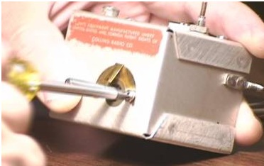
The stiff tuning problem could be caused by the misadjusted pinch drive at the end of the main tuning shaft. You can adjust this by removing the knob, then loosening the nut that secures the bushing to the front escutcheon. The bushing is “oblong” and can be rotated to raise or lower the tuning shaft and pinch roller. If this adjustment does not help, you probably need to clean and relube the main tuning coil L303. I describe a relubrication procedure below.
I have had two PTOs that drifted 2 khz or more during warm up, and didn’t settle down until after an hour. I have had PTOs that drifted only a couple hundred Hz and settled down after 30 minutes. I think the latter category is what is more normal behavior for a Collins PTO in new condition. I have cured this drift problem by replacing the 3000 pf. Mica capacitor and the .02 mfd bypass capacitors in two of my PTOs. Apparently with age or voltage stresses, they become more temperature sensitive than when they were new. The 1N34 diode can also be a culprit, causing drift with age. I describe the procedure for replacing these in a later paragraph.
These procedures are not as bad if one is careful. The PTO is remarkably forgiving. However, doing these procedures is at your own risk. You will need a magnifying lamp, solder wick, small tools and some patience. Think long and hard before you undertake this, but it is possible to service these PTOs, and actually quite easy after doing several of them. But if you do not feel you do not have the ability or time to do repairs like this, you should seek out one of the several individuals who are known to do repair work for Collins. (Refer to the CRA homepage: www.pixi.com/~jenkins/collins/ – editor) I have also not verified that these procedures totally agree with any documented Collins or other established maintenance procedures. They work for me though.
OPENING AND RELUBRICATING THE PTO
Removing the PTO
Whether you’re just going to do a relube, or also do the capacitor replacement, you will first have to remove the PTO from the radio. (Note: this is optional – you can do just the lubrication procedure with the PTO left in the set – editor) Carefully unsolder the leads from the PTO underneath the chassis. Remember where they went. On the 32S3, the PTO output (white coax) connects to a terminal behind the Freq. Control switch on the front panel. You will now need a set of Bristol (spline) wrenches to loosen the set screws for the tuning dial and other bushings on the PTO shaft. Loosen the set screws holding the large circular dial. Also remove the PTO mounting screws holding the PTO to the top of the chassis. Pressing gently against the back of the dial, the PTO shaft should slip out of the dial bushing. If it does not, a flat blade screwdriver inserted between the dial bushing and the brass bushing on the PTO shaft should be very gently worked to loosen and slide the dial off the shaft. Take care not to handle the plastic dial too roughly to avoid scratching the surface. Place the dial in a safe place out of the way. (this is the time to take apart the dial assembly and clean with mild dish detergent, if you wish – editor)
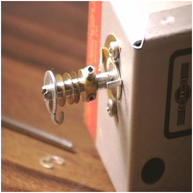
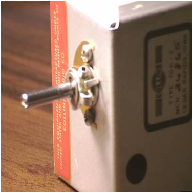
After removing the PTO from the radio, remove the C-ring, collars and shims from the shaft, being very careful to lay out the parts in the proper order on a cloth in secluded spot of the bench. (see the PTO illustrations – editor)
Now remove the back cover of the PTO box. You will see miscellaneous components and then the large cylindrical tuning coil that is also mounted with two long screws to the front of the box.
Opening the Main Tuning Coil
You are now going “inside” the PTO to clean and to relubricate the drive screw of the main tuning coil L303. Loosen the long screws holding it to the front of the box. If they don’t budge, they may be sealed with a spot glyptol in the back of the coil, in which case a little heat from the soldering iron applied quickly to the glyptol should soften it.
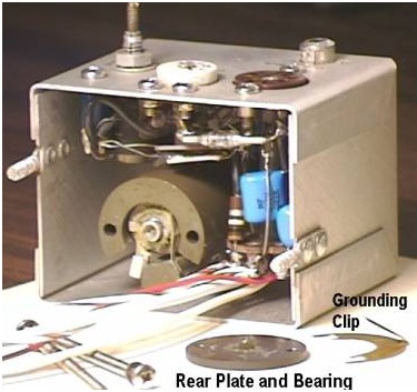
Once they are loose, hold the rear end of the large tuning coil with one finger while removing these two long mounting screws from the front. A copper grounding clip that mounts under these screws on the front should be removed and put in a safe place. The little circular rear plate will also come off the back of the coil in your hand.
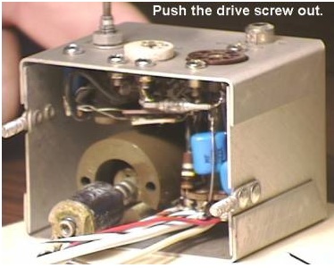
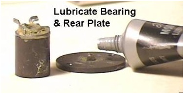
There is a nylon bearing at the end of the tuning lead screw (or it may be stuck to the circular plate). Don’t lose it! Clean the gunk off of it and put in a safe place (get a little dish or cup). Then push the front end of the shaft until the lead screw comes completely out the back,
Examining the lead screw assembly, you will notice that there is a cylindrical core that rides lightly from end to end of the shaft as you hold it and turn the shaft. You can twist this core all the way off and set it in your little dish.
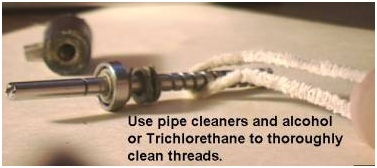
Next you will use some pipe cleaners and denatured alcohol to thoroughly clean the dried old grease from the end of the lead screw and its threads, and also the core if it looks dirty.
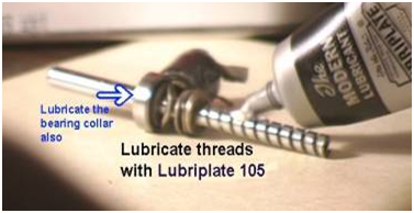
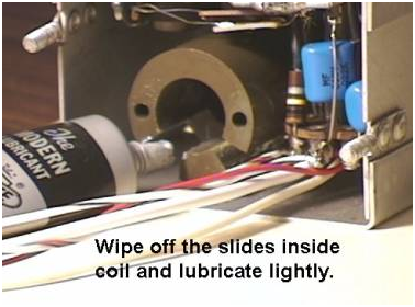
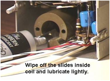
Clean up inside the coil cylinder too if it looks dirty. Then use a good quality white lithium grease to thoroughly lubricate the threads in the lead screw, its bearing collar, the core, and the inside of the coil housing. Not too much, just enough to make it turn smoothly. (Wal-Mart has this grease – editor)
Reassembling and Closing the Tuning Coil
Now if you don’t plan to do the capacitor replacement, go ahead and reassemble the PTO tuning coil as described below. If you are going to replace the capacitors, you will need to leave the coil disassembled for now and go to the next section below on capacitor replacement.
To reassemble the tuning coil, thread the core back onto the lead screw (with the little spring clips (tension tab) facing to the rear). The little tension tab on the back of the core will need to be VERY gently spread open slightly to allow the lead screw assembly to go back in.
| Gently push the lead screw and core assembly back into the coil housing. Again, be sure to put a little grease on the coil housing where the spring clips ride on the “slides” inside the coil housing, in the spiral drive screw, and also on the little nylon bearing and the center depression on the rear cover plate of the coil. Now put the bearing back where it belongs in the little depression there. It may be easier to keep the bearing in place by placing it on the drive screw with a nice gob of grease. Here is where it gets tricky!You need to use one hand to place and hold the back rear and bearing back onto the back of the coil housing. First be sure the bearing mates properly with the depression in the end of the lead screw, then press he plate to hold it there while you install first one and then the other long mounting screws from the front of the box. Tighten both slightly just enough to hold the cover in place. Place the stop collar back onto the shaft (see drawing). Then while pressing on the back of the coil, slide the copper grounding clip back where it came from under the two screw heads in the front. Then tighten the long screws. Just snug up – do not overtighten. Turn the shaft back and forth a little and be sure it is smooth feels right.
Replace the PTO back cover, but do not tighten the mounting nuts yet. Finally reinstall all the bushings, collar and shims onto the tuning shaft in the order they came off. Refer to the pictorials.
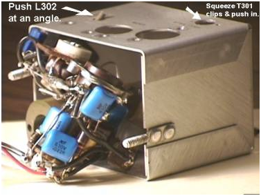
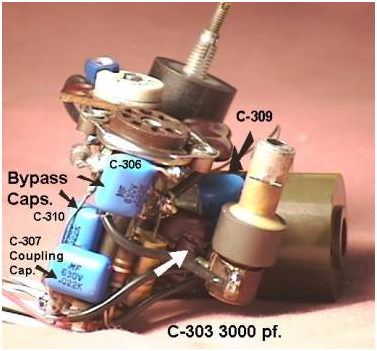
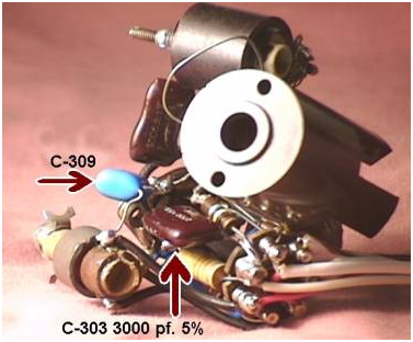
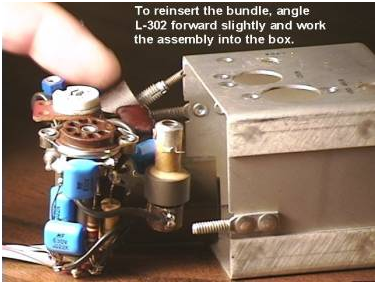
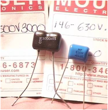
Reinstalling the PTO Now the PTO must be reinstalled in the radio. It’s a little tricky here too. Retrieve the plastic dial assembly. Thread the wires back down into the hole on the chassis and let the PTO lay loosely on top of the chassis. Hold the PTO up and slide the plastic dial back onto the tuning shaft, but leave the set screws loose for now. Be careful not to scratch it. Position the PTO so that the dial clears the dial cords etc. and becomes visible in the window. While doing this, ensure that the teeth on the plastic dial mesh properly with the idler gear on the rear of the front panel. The screw holding the idler gear can be loosened as needed to adjust. Also work with it to ensure that the pinch roller on the main tuning shaft mates properly with the inside groove of the tuning dial. Hold the PTO steady and reinstall the PTO mounting screws to the top of the chassis but do not tighten completely. Working with the PTO box in one hand and the tuning knob in the other, you should be able to move the box slightly horizontally and vertically until the knob turns the dial in a relatively consistent manner. When it feels good, tighten the rear mounting screws and the chassis top screws. These can be loosened and played with some more if necessary to tweak the pinch roller alignment. Now, resolder the PTO wires and double check all connections. By now you have probably noted that the alignment of the two plastic dials may be off. Some of the numbers on the rear dial may not appear properly between the white masked areas on the front dial. Not to worry, this can be adjusted. There is a black reference dot at the top edge of the dial that you can see if you look up at an angle into the front of dial opening. This dot should align with the 50 or 150 numbers. Turn the knob until you see this dot at the top of the dial window. If it doesn’t line up with 150, loosen (but do not remove) the screw holding the idler gear. Move the idler gear away from the teeth of the dial and then gently rotate the rear dial while holding the front dial stationary, until you see 150 centered in the window. Then tighten the screw holding the idler gear. (This procedure is a little tricky – you may have to remove the idler gear as a last resort if you can not remesh the gear to the teeth. I like to do this procedure at the “0” point – editor) Next you will need a known signal such as a low level tune carrier at a known frequency such as precisely 3900 Khz. Using the calibrator could cause you to align to the “wrong” 100 khz signal, so a single known carrier is preferred. With a low level test signal from a signal generator, etc. set at 3900 khz. fed into the antenna connector, tune the dial to 100. Then remove the tuning knob. While holding the plastic dial by hand (its set screws must still be loosened), use a small screw driver to turn the PTO shaft through the opening in front of the escutcheon. Hold the plastic dial and turn the shaft until you hear the reference carrier and zero beat it. Be sure the “100” aligns with the tuning hair (vertically) and tighten the dial set screws. You should then verify tracking of the PTO from end to end. By loosening the brass collar on the PTO shaft, you can adjust the end point stop excursion about 6.5 khz below zero and 6.5 khz above 200. The calibration should be very close at zero and 200 without having to change the hairline much. If not, you will probably need to repeat the end point spread adjustment (with L302) as described in your radio’s manual POTENTIAL CURES FOR WARM UP DRIFT Regarding drift, I have so far gotten two Radios (a KWM2A and a recently obtained 32S3) that experienced a large amount of warmup drift (2 khz or more) and a long warmup time, with questionable stability thereafter. I also have radios that exhibit a very small amount of warmup drift (less than 300 hz settling after a 30-45 minute warmup) which is far more gratifying to me than 2 khz. Some will argue that 2 khz warmup drift may be within the “specs.” and can be lived with, and that is true. But after this little experiment I do not believe the original Collins gear (with new components) drifted that much at all. I believe warmup drift of less than 200-300 hz is more the norm for what a “new” Collins radio would do. I received email from a couple of individuals who say that 200 hz or less was the typical warm up drift for a new radio. If the PTO is drifting less than about 500 hz (200-300 is more typical) during warmup, then it is probably good enough and you may not wish to do any more work on it.. When drift exceeded that significantly in two of my PTOs, I have found that a noticeable improvement in stability could be achieved just by replacing the .02 mfd bypass caps. inside the PTO. After that, I found that the 3000 pf cap. was suspect, at least on the two PTOs I have worked with here. I tend to suspect that aging of these capacitors could be a chronic problem causing this exaggerated warmup drift. Since I have only seen this effect with two PTOs, I am not aware of any other reasons for warmup drift such as this. Of course, other viable methods exist for helping the drift problem, such as cooling fans and solid state tube replacements. Capacitor Replacement Now if you’re going to replace caps, leave the main coil disassembled. Believe it or not, you can quite easily remove all the “guts” from a PTO in one piece. Just remove all the screws holding the tube socket, the trimmer cap, the main tuning coil, etc. and very gently work with the bundle of components to remove them from the box. All the components are wired together so everything comes out in one compact bundle. This does take some care, but once removed the components can be examined and replaced. Later, reversing these steps will gently reinsert the whole bundle into the box and appropriate holes (I think this is how they built them in the first place). Remove all of the other screws holding the tube socket, the trimmer cap, remove the nut holding L302, squeeze the clips on top of the T301 coil and push it down gently into the box, then tilt and slide the insides out onto the bench. When removing the bundle, be sure to push the two little coils down into their holes as you gently (emphasize gently) work with the bundle to ease it out. T301 is a little coil that clips into its mounting hole toward the front of the box. You must gently compress the clips from the top with your fingers or needle nose pliers and push it gently down into the hole. As you work the insides out the back of the box, also gently push down on L301 and angle it back slightly. It will then pull out with the rest. This electronic “glob” will then sit in one piece on the bench. It will even oscillate like that! Reinstall the in the reverse procedure, angling L301 slightly as necessary to work it back into its hole. If working on the “bundle” has caused mounted components like the tube socket, L301, T301, etc. to become pulled out of position, you should gently pre-position them as closely as possible to their final mounted positions before working the bundle back into the PTO enclosure. This is especially important so as to get the opening of coil, T301, aligned with adjustment opening in the aluminum top cover. To get T301 clipped back into its hole, I used the flat end of a plastic ball point pin which was larger in diameter than the coil to gently push up on it through the larger opening directly underneath it in the box. Then go to the steps above on closing up the tuning assembly and reinstalling the PTO. With two drifty PTOs, I have so far found the same causes: All of the “generic” .02 mfd. coupling or bypass capacitors C306, C309, C310 and C307 had aged. You wouldn’t think these simple B+ bypass caps would cause drift would you? Well, they did in my units. Apparently, as they change value with temperature, the RF load the oscillator tube (or its screen) sees looking into the B+ line changes, and hence the frequency. Before replacing them, I could cause several khz of drift just by cooling and heating these bypass capacitors. It is likely that they were fine when new, but with age and voltage perhaps they become more temperature sensitive. Replacing them a with quality temperature stable caps. made a significant improvement in stability, but still not good enough for me. The photo below shows the locations of these capacitors in a PTO that has just had new .022 mfd capacitors installed (blue). Some more probing with cooling spray revealed enough sensitivity from the 3000 pf C303 to warrant experimenting with a replacement for it also. This MUST be a high accuracy (5%) mica dipped capacitor for RF circuits. While you’re in there, replace the old 1N34 diode with a new 1N4148 or 1N4454. The old 1N34’s sometimes become leaky with age and cause noticeable warmup drift. After replacing all these capacitors and the diode on my two PTOs, warmup drift is now well below 200 hz. Before and after measurements were made with a counter. Note that this procedure does not touch any of the temperature compensated capacitors (C301, C305, C311) in the PTO. To replace these capacitors, you can clip out (or use solder wick to remove) the leads of the old caps and solder the new ones back in. Use very short lead lengths, no longer than the original ones. If an original capacitor had insulating sleeving on a lead, put sleeving back on the same lead of the replacement. After finishing, examine the bundle carefully to be sure there are no broken leads or shorts. Then slide the insides back into the box, close up the tuning coil (as above), install the long screws in the front, and reinstall all the other screws. You will need to angle L302 forward so it enters its mounting hole as you work gently with the bundle and coils to work everything back into place. Pull L302 completely up into its hole with your fingers. Manipulate the tube socket so it lines up with its opening. Grab the top of T-301 with a small screwdriver and gently pull it up into its opening until it clicks in securely (you can also push up on it through the opening underneath). And don’t lose that little bearing! (if you do, you can use a suitable small needle bearing – I once did – editor) The .02 caps. (C306-C310) I used were from Mouser P/N 146-630V.022K. They were advertised as high stability. They are a little larger (physically) than I would have liked but they all fit into the box OK. Their smaller 400V versions may be preferable. The 3000 pf cap is a mica dipped type. Suitable replacements can be ordered from Mouser Electronics – 3000 pf. 5% (Mouser P/N 5982-19-500V3000), or from Surplus Sales (SSN P/N CSM003000R00GGA – 2%, or SSN P/N CSM003000R00JGA – 5%). The 3000 pf. cap. you choose must be a precision 3000 pf. and not just “close.” I tried one that was more like 2700 pf and this capacitor shifted either end of the dial calibration by as much as several khz. If, after reinstalling and adjusting the end-point spread as described in the manuals, you can’t get the end point spread down with the L302 adjustment, the 3000 pf cap. you replaced may not be a correct value (if its is not 5% of 3000 pf, it may not be possible to pull the end point spread. Don’t use a generic .003 mfd. ceramic capacitors either They drift like crazy. Mica dipped only. My KWM2 manual showed a 5% tolerance for this cap., while my S-Line manuals showed 1% tolerance. While I have successfully used 5% in the PTO’s I serviced here, I would recommend finding a tighter tolerance component if available (1-2%). Also note that some Collins schematics show a 2000 pf cap. here instead of 3000. I believe this is a typo, but check the value in your PTO to be sure and replace it with a dipped mica type of a matching value.
|
