32V-2/3
THE COLLINS 32V-3 TRANSMITTER
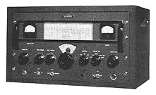
The 32V-3 transmitter is nearly identical to the earlier model 32V-2 from 1949. The 32V-3 incorporated improved RF shielding which included a lidless metal cabinet, re-shaped ventillation holes, and additional meter and AC line shielding. Rack handles were also added to make removal from the cabinet easier. It is also absent the CW sidetone oscillator present in the earlier 32V-2.
The type 32V-2 is a transmitter designed for those amateurs who want medium power, bandswitching, and VFO control in a small cabinet. It may be used for either permanent or portable installations. All that is needed for putting it into operation is a 115-volt a-c source, an antenna, and a key or microphone. The 32V-2 can also be used to drive a kilowatt final amplifier.
The 32V-2 transmitter is designed for table mounting. The complete transmitter is housed in a single cabinet 21-1/8 in. wide, 12-7/16 in. high and 13-7/8 in. deep and weighs approximately 105 lbs. Ventilating openings are provided in the back, two sides and bottom of the cabinet to assure adequate ventilation for all heat producing elements.
The components of the transmitter are so arranged that unit construction is possible, and they are broken down in five units as follows:
70E-8A Oscillator R-F Unit Output Network Speech Amplifier and Modulator Power Supply
All wiring is independent of the cabinet, and the complete unit may be removed from the cabinet for inspection or maintenance.
Complete coverage of the 80, 40, 20, 15, 11, and 10 meter bands is obtained with the 32V-2. Quick band change is accomplished by bandswitching on all stages. The permeability tuned circuits of the 1st, 2nd, and 3rd multipliers have their tuning controls ganged with the oscillator. The final tank consists of impedance matching network with two separate controls located on the front panel, one for tuning and one for loading.
Two heavy duty toggle switches control the low voltage and high voltage circuits. The switches are arranged to that the high voltage cannot be applied until the low voltage circuits have been energized. A push-to-talk switch, associated with the microphone, may be used to apply the high voltage instead of the HV toggle switch for added convenience.
A CW sidetone oscillator is incorporated in this unit with which CW transmissions can be monitored. An additional feature, the receiver muting connection, can be used to silence a type 75A receiver during CW transmission for CW break-in operation.
A meter selector switch on the front panel enables the operator to meter all important circuits of the transmitter. This switch can be rotated to five different positions. Each position inserts a meter into the selected circuit to be metered. A separate meter reads FINAL AMPLIFIER plate current only. The CW-CAL-PH switch is used to select the type of emission desired and to calibrate the accuracy of the dial reading against a known standard frequency. In the CW position, the modulator is disabled, the master oscillator operates continuously with the HV switch on, and the CW sidetone oscillator is connected to the audio amplifier stages. On CAL position, a signal of strength suitable for zero-beating with incoming signals may be heard in the associated receiver without operating the final amplifier. On phone position, the key is closed and the modulator is operative. Keying is accomplished by means of grid block keying of the buffer stages. This keying is done on the buffer and first and second multiplier stages.
The AUDIO GAIN control is used to control the level of modulation and the strength of CW sidetone output.
32V-3 SPECIFICATIONS
Power Source …………. 115 volts as 50/60 cps single phase.
Power Input Requirements . The maximum over-all input power requirement is 500 watts
at 90% power factor.
PA Plate Power Input ….. The nominal rated power input of the 32V-2 is 120 watts on phone
and 150 watts CW.
Audio Distortion ……… Audio distortion is less than 8% at 90% modulation with a 1000-cps
input frequency.
Frequency Response ……. Within 2 db from 200-3000 cps.
Under the hood…
32V-3 CIRCUITRY
OSCILLATOR – A type 6SJ7 tube is employed in a highly stabilized master oscillator circuit to generate the controlling radio frequency voltage. This frequency generating unit is a linearly tuning permeability tuned oscillator with a range of 1.6 to 2 megacycles. Sixteen turns of the main tuning dial cover this range. This provides 50 kc per revolution of the second harmonic (3.2 to 4 mc band). With the end points properly set up, the tuning curve is linear within one dial division of the ideal tuning curve on any of the bands in the operating range. The oscillator circuit is compensated for temperature changes and is entirely enclosed in a heavy aluminum case.
INTERMEDIATE STAGES – Following the master oscillator, a type 6AK6 is employed in an untuned, Class A amplifier stage. This stage completely isolates the master oscillator from the remaining tuned stages. The 6AK6 drives a series of three frequency multiplier tubes, the first of which is a type 6AG7.
Plate screen and filament power for these stages is obtained from the low voltage power supply. Gang tuning of the multiplier stages is obtained by moving powdered iron cores, attached to a common platform, in and out of the plate coils which are wound to give linear tuning. This platform to which the iron cores are attached is also ganged to the master oscillator tuning for complete, single control tuning of the exciter stages. Band switching is accomplished by adding extra padding capacity across coils by means of the band switch in all cases excepting the 14-mc output of the third multiplier where an inductance is switched in parallel with the existing 40 meter inductor to lower the tuning inductance for 14-mc output.
POWER AMPLIFIER STAGE – A type 4D32 tetrode power amplifier tube is used in the PA stage. This tube always operates as a straight amplifier. The plate circuit is tuned by a combination pi-network and “L” network which is band switched along with the multiplier stages. The combination network reduces the output impedance to around 50 ohms on all bands by means of inductance and capacitance switching. The output network will actually operate satisfactorily with antenna impedances in the range 26 to 600 ohms. It is also effective in reducing harmonic output of the transmitter. The screen grid and plate of the 4D32 are both modulated in phone transmission. Plate and screen voltage is obtained from the high voltage supply, while filament power is obtained from the low voltage plate supply transformer. The tube is biased with 75 volts of fixed bias plus some grid leak bias.
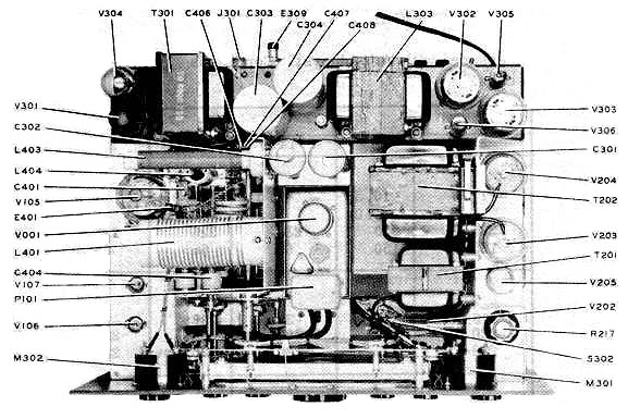
AUDIO CIRCUITS – The first and second audio amplifier consists of a type 6SL7 tube operated as a cascade amplifier. A volume control, R205, is located in the grid circuit of the second amplifier stage. The driver stage employs a type 6SN7 tube with the two triode sections operated in parallel to drive the modulator stage. The modulator stage utilizes a pair of type 807 tubes connected in a push-pull circuit and operating class AB2. The output of the modulator is coupled to the final amplifier by transformer T202 to modulate the plate and screen of that stage. During CW operation, the secondary of the modulation transformer is shorted out by S302A. Bias for the modulator tubes is adjustable by R305, and obtained from the low voltage supply and regulated by the voltage regulator tube, V304, type VR-75. The secondary of the modulation transformer has a 500-ohm tap provided for supplying 60 watts of audio power to an external load.
HIGH VOLTAGE SUPPLY – The high voltage transformer is energized when the contacts of relay K301 are closed. The high voltage supply employs IWO type 5R4GY rectifier tubes connected in parallel in a full wave circuit The output is filtered by a single section choke input filter. This supply furnishes voltage for the plate and screen of the final amplifier and plate voltage for the modulator tubes. The amount of output voltage from this supply may be either 600 volts or 700 volts depending on the position of the tap switch, S305, in the primary winding of the high voltage transformer T302. For the same power input, the efficiency of the final amplifier improves with the higher operating voltage. The tube manufacturer recommends no more than 600 plate volts for phone operation, but this is for CCS rating. A pair of 15-ohm resistors are connected in series with the HV plate transformer primary for “tune-up”. The series resistors are shorted out when operating.
LOW VOLTAGE SUPPLY – Transformer T301 furnishes power for both the low voltage plate supply and the filament of all tubes in the transmitter. The T301 is energized by closing the LV switch, S304. Three separate windings on transformer T301 furnishes filament power to the tubes. The low voltage plate supply employs a type 5Z4 rectifier tube in a full wave circuit with a two-section choke input filter. This supply has a total output voltage of approximately 315 volts; 240 volts is supplied to the audio amplifier, oscillator, buffer and multiplier stages. Bias voltage for the modulator and final amplifier stage is furnished by this supply. It also supplies voltage for the operation of relay K301.
RECEIVER MUTING CIRCUIT – Users of the Collins Model 75A receiver can take advantage of the CW muting circuit contained therein. This muting is accomplished by blocking the noise limiter circuit in the receiver with a positive voltage. In the 32V-2 transmitter, this positive voltage is obtained from the voltage drop across the cathode resistor of the second multiplier tube, V103. The receiver limiter switch should be in the OUT position during CALIBRATION adjustments of the 32V-2 and in the IN position when muting is desired on CW operation.

