51S-1
Copyright 2013-2016 Collins Collectors Association

51S-1/1A/1F/1AF/1B RECEIVER – An Overview
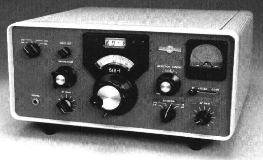
The 51S-1/1A/1F/1AF/1B receiver is designed for USB, LSB, AM, and CW signals in the range of 0.2 to 30.0 MHz. Coverage is continuous in thirty 1 megahertz bands. The more common models of the 51S-1 are mounted in a perforated wrap-around cabinet and equipped with an AC power supply capable of 115 or 230 volt, single-phase, 50 to 400 Hz operation. The 51S-1A is similar, except that it is fitted with a 28-volt DC transistorized power supply. The rack-mounted AC version is model 51S-1F, while the rack-mounted DC version is model 51S-1AF. The 51S-1B is similar to the 51S-1, but has a rear-mounted junction box that provides military-type connectors for power, control, audio, and antenna lines. The -1B is a rare bird – indeed.
For a Detailed Physical & Operational Description – Click Here or click on the Equipment of Collins Radio on our Home Page and follow the Grey Box trail.
This receiver, while appearing to be a member of the notable “S-Line Family”, is not really an S-Line receiver at all. It is better thought of as the next model following the A-Line era 51J-4 (and never introduced 51J-5, see Q3 2013 Signal). From an architectural perspective, and from a construction and fundamental mechanical design standpoint, it is also very different from an S-Line receiver. It does share many features, including the styling of the cabinet and the PTO size and style, but the 51S-1 PTO is a 70K-7 as opposed to the 70K-2 used in the S-Line family. The 51S-1 variants are all continuous coverage (with up to triple conversion in some frequency ranges), while the various members of the S-Line family of receivers are double conversion and ham band oriented. Yes, of course, they too can function anywhere from 3.4 to 30 MHz when re-crystaled.
The 51S-1 was not part of the original package of defined S-Line products. At the time that these products were developed, and for many years, the same engineering group had responsibility for the HF commercial as well as amateur radio communications products. This group was headed by one Gene Senti, W0ROW, of – among other things – KWM-1 and 30L-1 fame. He also had a very strong personal love for receiver conversion scheme development and “Birdie” analysis.
Well into the period when the S-Line initial offerings (based around the 75S-1, 32S-1, 516F-2, KWM-2, and 312B-4) were being developed and readied for production in 1959 – the 51S-1 concept came into being. You will remember that the entire S-Line was defined in late 1956 and early 1957, and then developed throughout 1957 and 1958. The S-Line was then introduced in production late in 1958 and early ’59. The KWM-2 went into production in November of ’59, and finally the 30S-1 amp in the July 1960. Ed Andrade, a key engineer responsible for much of the KWM-2 and 30S-1 transfer work (and working for Gene Senti at the time) was multitasking the 51S-1 development with the 30S-1.
We know how the 51S-1 concept was born. It all started well into the development work on the S-Line, and the story goes like this: Chuck Carney, W0GDJ (now SK – and then the manager of the marketing organization responsible for the commercial and amateur radio HF products), was walking down the hall in the engineering building with Gene Senti, W0ROW and Ed Andrade, W0DAN. Ed Andrade made the comment that the 51J-4 was getting a little long in the tooth and that he thought they could now “Do Better”. Both Gene and Chuck agreed, and the 51S-1 seed was planted. Gene and Ed went back to their offices and started discussing what such a receiver would look like. Remember they were in the middle of the S-Line development – hot and heavy. Gene, as he loved to do, worked out a conversion scheme and the associated birdie chart, and Ed worked on the tube lineup and the stage and total receiver gains. A block diagram soon emerged along with the associated stage gain distribution and the birdie analysis. The basics were in place. Excitement grew internal to the engineering group, but the little receiver never got a formal engineering project authorization – a fact that almost killed it about a year later.
Dennis Day, W0ECK (then an engineer under Gene and one day to become his replacement), returned to Collins Radio in May of 1960 after getting married and finishing graduate school. He relates that soon after he returned to his job with Gene’s group, Joe Jekerle, W0OEU (one of the key lab technicians), completed building up several lab models of the 51S-1. They were very close to turning them on and to seeing how they worked when Bob Cox, Gene Senti’s boss, came through one day and discovered the work for the first time. There was no authorization for the project, and it got immediately shut down…..or so Bob thought. Gene, taking some risk to be sure, continued to build out these lab models until they were ready to function…..and function they did. Everyone was so impressed with the performance and “the sound” of the little rig that they jacked up their nerve and summoned Bob Cox to show him the new receiver. At that time, things could have gone either way and the team kept their fingers crossed. Fortunately, Bob Cox was also very impressed and commenced the process of “selling it upstairs”. Art was so very impressed when he saw the new receiver that it became a “must have” and the 51S-1 became a reality. It was a serendipitous accident that the S-Line and its new “Industrial Design Influenced Styling” was in process at the time. The “could have been 51J-6 (sic)” became the 51S-1.
Jerry Vonderheide, W0NGL, took over as the “collateral” production engineer when the 51S-1 was transferred to production. The 51S-1 was announced and began appearing in price lists in 1962. The Rev 0 manual is dated 1961. The first build of volume was in the Anamosa, Iowa factory in 1962. It is also interesting to note that, between the introduction in 1962 and 1975 when production was slowing down, Collins only promoted the 51S-1 twice in their top amateur radio advertising venue, QST Magazine. The receiver was expensive, and while the new little radio carried an “S-Line” number, it was not promoted actively as a part of the S-Line amateur radio offering. It was far too expensive for all but the wealthiest amateurs.
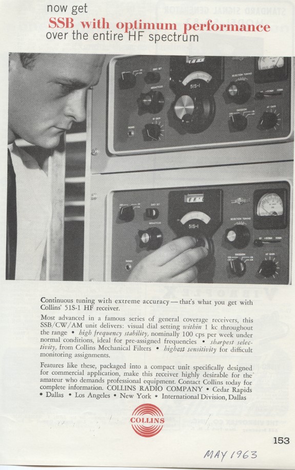
QST, May, 1963 First QST ad since intro
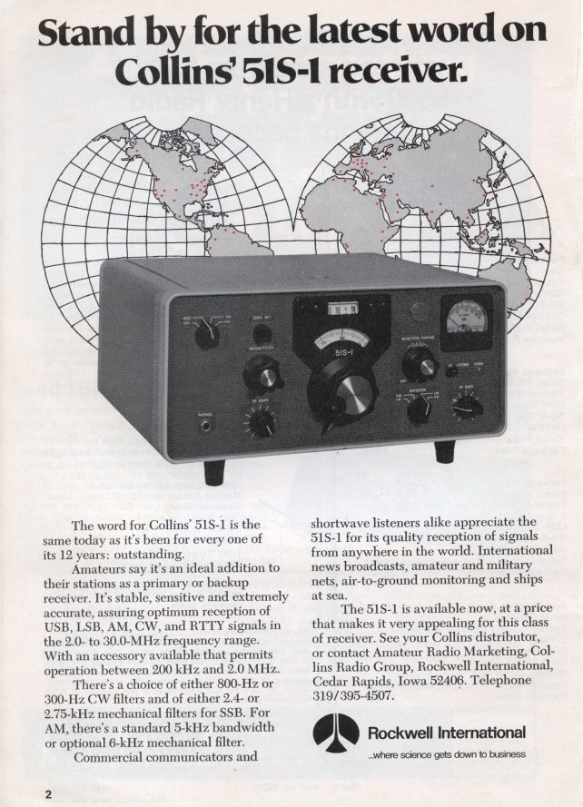
QST, July, 1975 Next QST to appear
The 51S-1 went on to become very successful. It was, indeed, adopted by many wealthy hams as their choice for a top notch general coverage receiver. It also became the receiver of choice for embassies, the intelligence community, and U.S. and foreign government agencies in general – including many applications in the Army and Air Force. The Mil versions were given new model numbers – the R-1122 (AC Supply and in a Cabinet), R-1156 & 56A (DC Supply, Rack Mount), and the R-1483 (51S-1A DC Supply and Cabinet). There were also Air Force contract versions that had military style connectors in place of the commercial standard versions. These were not assigned a MIL number but done under a special contract.
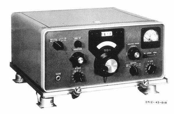
51S-1B Airborne/Mil Model with 350D-5 Shock Mount Accessory
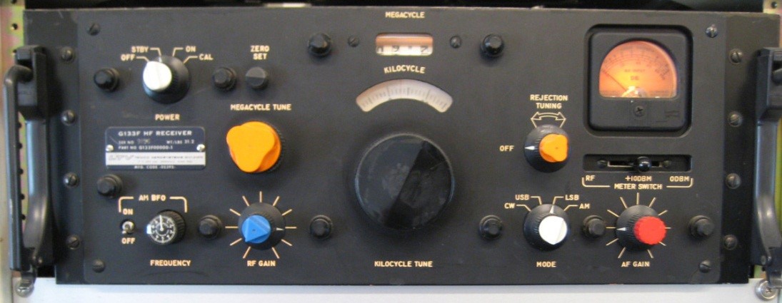
LTV G133F-1 Intelligence Modification
The 51S-1 was bought and modified by Ling Temco Vaught (LTV) under a military contract to provide an intel intercept and monitoring receiver. The modifications added airborne mounting and interface capability and another layer of noise filtering on all I/O lines. In addition, this modification by LTV jazzed up the user interface to make its functionality more clear in reduced lighting and airborne applications. In application, the G133F-1 was part of the ARDF QRC-346 System.
Rod Blocksome has provided us with a wonderful article (See p 10 in this issue) that gives us a significant amount of historical data including where the receiver was manufactured, the different variations and serial number ranges involved as well as the military designations and details for the military 51S-1s. This article also gives considerable insight into the prototyping and development phase of the birth of the little receiver as well as detailing the manual revisions, to which date range they belong, and the Service Bulletin history.
51S-1 Receiver Models and Variations
| Model | Top Level CPN | No. of CPN | Package | PS | Notes |
51S-1 |
522-2245-xxx |
18 |
cabinet |
AC |
R1122/GR |
51S-1A |
522-2546-xxx |
17 |
cabinet |
DC |
R1433/UR |
51S-1B |
522-3857-xxx |
2 |
cabinet |
DC |
Mil Connectors; USAF – no mil nomenclature |
51S-1F |
522-2498-xxx |
18 |
Rack mount |
AC |
R1156/GR (522-2498-00)R1156A/GR (522-2498-030) |
51S-1AF |
522-3156-xxx |
17 |
Rack mount |
DC |
|
51S-1BF |
522-3850-xxx |
1 |
Rack mount |
DC |
Mil Connectors |
The Collins 51S-1 HF Receiver – Feature article by Rod Blocksome, K0DAS, containing development details and details of variations, production volumes and manufacturing locations
Click Here for the 51S-1 Manual and included schematics – See Manual Listing for a complete selection of Manuals, Service Letters and Service Bulletins
Figure 1. 51S-1 Block Diagram

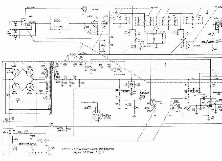
Figure 2. Front End Switching and Conversion Partial Schematic
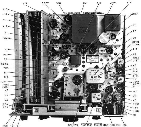
Under the Hood
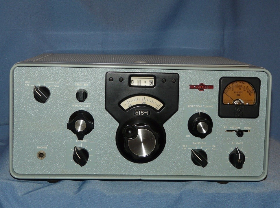
Discovered in New Zealand in 2012, this may be an example of the “Grey” panel.
Over 12,360 units total were produced between the introduction in 1961 and close of production in 1982. This is a very long production run for any radio and the highest production quantity of any of the 51J-x series – even if you combine the total production of the 51J-3 and the R-388 series (which totaled just over 10,000).
The very early receivers had variations in the number of knob flutes (5 in place of 4 on the Megacycle knob) and also some panel marking width variations around the Rejection Tuning. These same early receivers also used the 70K-4 2 tube PTO – while the bulk of production used the 70K-7. The serial numbers ran sequentially throughout production including across top level CPN build changes until 1975. This is true with the exception of one block of 124 serial numbers which, for some reason, was either not used early on, or was used on a non-standard model like the F. This block of lower numbers was then used later for the standard 51S-1 – around 1975. After 1975, serial numbers were assigned by build. Over 10,000 51S-1s were built as the rather standard 51S-1, 51S-1A and 51S-1AF. There were even some 51S-1s built with Spanish labeling on the panels.
51S-1 Service Bulletin 4, dated August 9, 1965, added the dial brake assembly. See the Manual and Service Bulletin listing for other service related bulletins.
The winged to round logo transition occurred in the fall of 1969 and there were 5 different logo badges attached to the 51S-1 models over its production span. Early units carried the winged emblem until 1969. The subsequent units carried a smaller round emblem and then the larger round emblem until 1976. Then, following Rockwell’s acquisition of Collins, the emblem changed to the well-known Terra Cotta with White lettering Rockwell Collins emblem followed by one with Blue Lettering.
Accessories associated with the 51S-1 Series
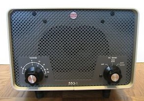
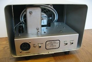
55G-1 Introduced in ?? Late 60s or early 70s…..need manual rev 0 check on intro – thought earlier than Rod’s survey suggests.
351E-4 Table Mount
350D-5 Shock Mount
351R-1 Rack Mount
351R-2 312B-3 Speaker Rack Mount
312B-3 Speaker
312C-1/2/3 Rack Mount Speaker options (1,2 or 3) for the 51S-1
Special Filters AM & SSB
55G-1 LF Preselector
Special Thanks to Rod Blocksome, K0DAS, Larry Saletzki, WA9VRH and Charlie Talbot, K3ICH for their contributions. Edited by Bill Carns, N7OTQ
– – – – – – – – CCA – – – – – – – –
Note: The images and text used in these pages are copyright 2013 – 2016 protected, are restored and written by the Collins Collectors Association or its representatives, and may not be used in any other commercial or website applications. They may be downloaded and used privately – not for publication or internet use.
- CCA COLLINS HISTORICAL ARCHIVES
- The Pre War Years
- The War Years
- Post War Broadcast / Commercial
- The Black Boxes
- The Grey Boxes
- 30L-1
- 30S-1
- 312B-4/5
- 32S-3
- 51S-1
- 51S-1 Detailed Physical & Operational Description
- 51S-1 HF Receiver - Blocksome
- 62S-1
- 75S-3B
- Collins Microphones
- KWM-1
- KWM-1 Accessories
- KWM-2/2A Accessories
- KWM-2/2A Transceiver
- S Line Accessories
- The “S” Word or Solid State