51S-1 HF Receiver – Blocksome
By Rod Blocksome, K0DAS
A number of years ago I conducted surveys of Collins ham equipment on the CCA reflector. The project was designed to shed light on the many questions collectors had about production quantities, anomalies, scarcity, etc. I published the results on the reflector and, in the years since, I have continued to gather additional data from other sources. This article is an update – along with some additional information and insight added.
I would like to acknowledge the project engineer who led the design of the 51S-1 receiver. It was none other than Ed Andrade, W0DAN – The same fellow who earlier brought forth the Collins 51J-4 and the KWM-2! All three equipments were in production far longer than the average Collins HF equipment – a testimony to the solid design and outstanding performance achieved by Ed and his engineering team. Jerry Vonderheide, W0NGL, later created the 51S-1A – a version powered from 28 Vdc for aircraft operation.
Several years back, an engineer from Ed’s 51S-1 team retired and asked me if I would be interested in the prototype 51S-1 receiver. I accepted of course and spent some time examining the unit, taking photographs, and even contemplating restoring it to operating condition. But after further thought, I decided it was really a historical artifact and shouldn’t be tampered with. So I did some minor cleaning and then put it on display in the Rockwell Collins Museum. Figure 1 shows the front of the radio. One can see several items that are much different than the production versions we are used to seeing. For example it has a noise blanker although the module was missing from the chassis. The main tuning knob is machined from solid brass and painted black. Arlo Meyer, W0LBK, told me they wanted the feel of a weighted knob for tuning but it was going to turn an extensive gear train.
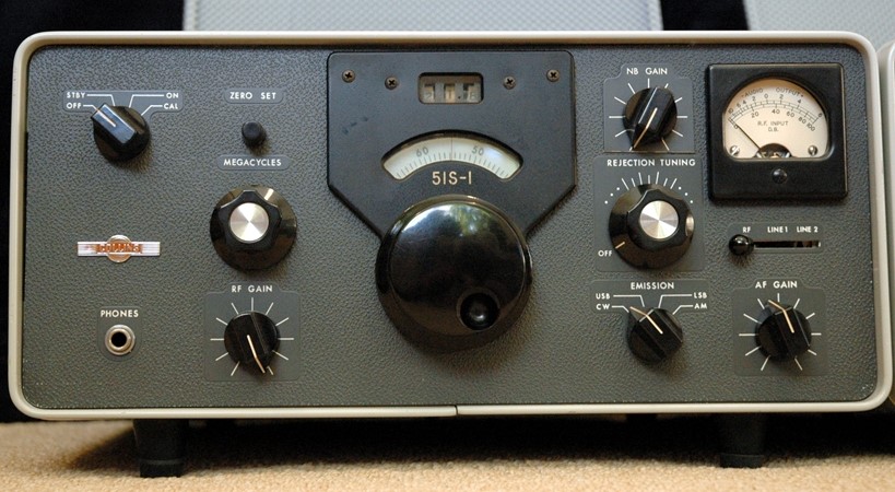
Figure 1 – 51S-1 Receiver Prototype
In addition to the main tuning knob, a list of other changes includes:
The “Zero Set” knob is round like the S/Line instead of the small “bar” type used in production.
The Collins logo is located above the phones jack.
The noise blanker knob is located where the production logo was later placed.
The “Rejection Tuning” scale has expanded tic marks.
The meter switch is labeled “RF, Line 1, Line 2” (The prototype had two line audio outputs).
Under the hood things are similar but different in a few areas as shown in Figure 2 where the prototype on the left is placed beside a 1963 winged emblem production model for comparison.
The prototype cabinet is a modified KWM-2 cabinet (obvious from the rear).
The rear panel connections are different.
It has a five fluted Megacycle knob (Early production 51S-1 were the same and then it was changed to four flutes).
There is a tuner shield with holes for alignment and a tube stage on the left.
There are two lamps on the PTO dial.
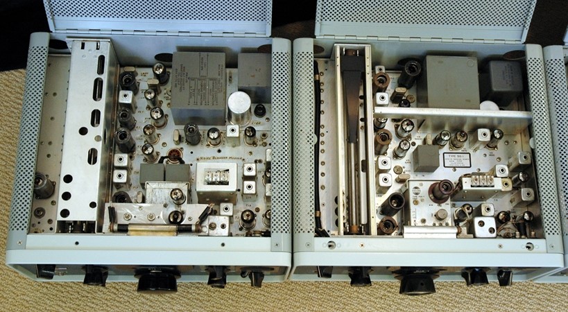
Figure 2 – 51S-1 Receivers – Prototype on the Left
The first production of the 51S-1 occurred in August 1961 when three units were completed just before the end of fiscal year 1961. But things started to roll in 1962 and continued for 20 years. By the time production ended, some 12,136 51S-1 receivers came forth from the Collins factories by my count & estimates. Tables 1 and 2 provide details resulting from my research into the production history of this fine radio.
Table 1 – Production Quantities of 51S-1 Receivers
| Fiscal Year 1 | Production
Location |
51S-1 | 51S-1A | 51S-1B/BF | 51S-1F/AF | Total |
| 1961 | CR/Anamosa | 3 | 0 | 0 | 0 | 3 |
| 1962 | CR/Anamosa | 262 | 0 | 0 | 86 | 348 |
| 1963 | CR/Anamosa | 410 | 9 | 0 | 192 | 611 |
| 1964 | CR/Anamosa | 486 | 14 | 1 | 283 | 784 |
| 1965 | CR/Anamosa | 306 | 39 | 90 | 350 | 785 |
| 1966 | CR/Anamosa | 430 | 133 | 90 | 289 | 942 |
| 1967 | CR/Anamosa | 758 | 38 | 177 | 378 | 1351 |
| 1968 | CR/Anamosa | 535 | 4 | 148 | 324 | 1011 |
| 1969 | CR/Anamosa | 515 | 0 | 103 | 260 | 878 |
| 1970 | CR/Anamosa | 557 | 13 | 9 | 132 | 711 |
| 1971 | CR/Anamosa | 543 | 12 | 12 | 196 | 763 |
| 1972 | CR/Anamosa | 569 | 0 | 21 | 137 | 727 |
| 1973 | CR/Anamosa | 315 | 3 | 4 | 115 | 437 |
| 1974 | CR/Anamosa | 621 | 7 | 0 | 237 | 865 |
| 1975 | CR/Anamosa | 350 | ||||
| 1976 | Richardson, TX | 550 | ||||
| 1977 | Toronto, ON | 100 | ||||
| 1978 | Toronto, ON | 170 | ||||
| 1979 | El Paso, TX | 250 | ||||
| 1980 | Salt Lake City, UT | 200 2 | ||||
| 1981 | Salt Lake City, UT | 200 2 | ||||
| 1982 | Toronto, ON | 100 2 | ||||
| TOTAL | 12,136 |
Note 1 – The Collins fiscal year ran from 1 Sep. to 31 Aug. until 1974 when it was changed to run from 1 Oct to 30 Sep. Therefore FY1974 was 13 months long (1 Sep. 1973 to 31 Sep 1974).
Note 2 – Very little data has been found for FY80 – 82. These are best estimates.
In general the serial numbers were not purposely scrambled on the 51S-1; however, there are strong indications in the data that around 1975 some 124 51S-1’s were assigned early serial numbers that were likely used for other types (e.g. 51S-1F). The reason is unknown. Other than this instance, the serial numbers are sequential without regard for specific type number until 1975 when different serial number blocks were used for unique 51S-1 types. Production ran to about 1982, but no data has been found for units produced after 1979, so I’m estimating 500 units for 1980 and beyond.
On most receivers you will see an “MCN” followed by several digits. This is the Manufacturing Control Number and is used for configuration and revision control as the equipment progressed through the manufacturing process. Only after a manufactured unit has passed final test and quality control inspection is a serial number affixed to the radio. The system of assigning and even marking MCN numbers on the unit changed over time. There is not a lot of MCN data available to draw firm conclusions but it appears as though the MCN numbers were only unique for a given top level part number. Then starting in 1975, someone decided to simply use the MCN number as the serial number. At that point the MCN was probably unique for all flavors of 51S-1 receivers.
A caution in using the MCN to analyze serial number and production quantities: It was common practice to do “Spec Builds”. In other words – produce radios that did not have an immediate customer order. These units would go into finished goods inventory until sold. Frequently a customer order later would come in for a few radios of a certain “flavor” but finished goods contained only radios of a different “flavor”. Often the solution was to pull the finished goods radios and run them back through the factory to be reworked into the flavor ordered by the customer. In this situation the radio would receive a new serial number, new top level part number, and perhaps a new model type, but the original MCN would remain.
The 70K-7 PTO also carried the Collins Logo and an MCN. It is interesting to note that the PTO changed to the Collins Round Emblem (or “meatball” as it was affectionately called) in 1961 when all the other Collins Products made the change – except for the amateur equipment and the 51S-1 receivers. They continued using the winged emblem up until the fall of 1969. A lot of equipment was in process on the factory floor when the edict came down that “nothing goes out the door with the old logo”. To avoid scrapping a lot of front panels, the engineers came up with the idea of placing two tiny grey screws on either side of the meatball to plug the holes used for the former winged emblem. Thus the so-called “RE-Transition” was born.
The MCN on the PTO is another analysis guide to determine receiver quantities. But remember spare PTO’s were built and shipped to customers with their own maintenance shops. Also an early serial number receiver will occasionally have a PTO with a late MCN – usually the result of PTO replacement somewhere along the line.
Table 2 – Serial Number Model for Production History
| Fiscal Year | Logo Emblem | Serial No. Range | Production
Location |
| 1961 | Winged | 1 – 3 | CR/Anamosa |
| 1962 | Winged | 4 – 352 | CR/Anamosa |
| 1963 | Winged | 353 – 964 | CR/Anamosa |
| 1964 | Winged | 965 – 1749 | CR/Anamosa |
| 1965 | Winged | 1750 – 2535 | CR/Anamosa |
| 1966 | Winged | 2536 – 3478 | CR/Anamosa |
| 1967 | Winged | 3479 – 4830 | CR/Anamosa |
| 1968 | Winged | 4831 – 5842 | CR/Anamosa |
| 1969 | Winged; RE-transition | 5843 – 6721 | CR/Anamosa |
| 1970 | RE Large & Small | 6722 – 7433 | CR/Anamosa |
| 1971 | RE Large & Small | 7434 – 8197 | CR/Anamosa |
| 1972 | RE Large & Small | 8198 – 8925 | CR/Anamosa |
| 1973 | RE Large & Small | 8926 – 9363 | CR/Anamosa |
| 1974 | RE Large & Small | 9364 – 10229 | CR/Anamosa |
| 1975 | RE Large & Small | MCN12000 – MCN12224 (note 1) | CR/Anamosa |
| 1976 | RC & variations | 13000D – 13985D (note 2) | Richardson, TX |
| 1977 | RC & variations | C30,000 – C30,099 (note 3) | Toronto, ON |
| 1978 | RC & variations | C30,100 – C30,269 (note 3) | Toronto, ON |
| 1979 | RC & variations | T5001 – T5250 | El Paso, TX |
| 1980 | RC & variations | ? | Salt Lake City, UT |
| 1981 | RC & variations | ? | Salt Lake City, UT |
| 1982 | RC & variations | ? | Toronto, ON |
Note 1 – There is evidence that some 124 random unused serial numbers were used in FY1975 in addition to the series shown.
Note 2 – It is unlikely Richardson produced nearly 1,000 radios, therefore assume some numbers were skipped.
Note 3 – There is evidence of the same serial number in this range being assigned to different receiver type numbers e.g. 51S-1 and 51S-1F.
The 51S-1 series receivers consist of several different types and within each type there are minor variations denoted by a difference in the last three digits of the Top Level Collins Part Number. Some also have military nomenclature as shown in Table 3.
Table 3 – 51S-1 Receiver Models and Variations
| Model | Top Level CPN | No. of CPN | Package | PS | Notes |
| 51S-1 | 522-2245-xxx | 18 | cabinet | AC | R1122/GR |
| 51S-1A | 522-2546-xxx | 17 | cabinet | DC | R1433/UR |
| 51S-1B | 522-3857-xxx | 2 | cabinet | DC | Mil Connectors; USAF – no mil nomenclature |
| 51S-1F | 522-2498-xxx | 18 | Rack mount | AC | R1156/GR (522-2498-00)
R1156A/GR (522-2498-030) |
| 51S-1AF | 522-3156-xxx | 17 | Rack mount | DC | |
| 51S-1BF | 522-3850-xxx | 1 | Rack mount | DC | Mil Connectors |
Very early units (about the first 130 units) sported a 5-fluted Megacycle knob and wide spaced lines around the Rejection Tuning knob. These early radios also used the 70K-4 two-tube PTO. After that, all receivers used the 70K-7 single-tube PTO.
There were a variety of meter faces scattered throughout the production history. In general they follow this pattern:
Early WE – White Meter Face
Late WE – Yellow/Amber Meter Face
Late RE and RC – Red or Orange Meter Face
The Collins Logo emblems run the gamut – Winged Emblem from 1961 to the fall of 1969; Round Emblem Transition fall of 1969, Small RE (about size of a dime) from fall 1969 to about 1975, Large RE (about size of a nickel) through FY 1976, Rockwell Collins with terra cotta “Collins” & white “Rockwell” to the end except for a few with blue “Rockwell” from about 1980. A third Rockwell-Collins emblem has recently surfaced. It is square with all terra cotta color and the only word is “Rockwell”. It carries a serial number indicating it was manufactured in Richardson, TX probably in 1976. So there you have it – a grand total of seven different emblems to collect!
Front panel variations abound: Green front panels; Panels labeled in Spanish, and (hold onto your hats) the G-133F receiver from Ling-Temco-Vaught (LTV) began life in the Collins factory as a 51S-1. It is unknown if these units carried serial numbers in the 51S-1 sequence or even how many were produced.
How many front panel colors can a 51S-1 come dressed in? Believe it or not – there were a total of six colors per the list below.
Dark Gray: Per Collins PN 580-0182-00 (The most common color)
ICF Gray: Color #26440
FAA Gray-Green: Per Collins PN 580-0342-00
Gray: Per Collins PN 580-0255-00
Green: Color #24325
Gray Enamel: Per Collins PN 580-0236-00
Only a few units probably used these variations. But if it looks strange – don’t repaint it – it just might be original!
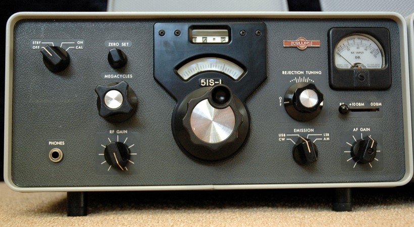
Figure 3 – Winged Emblem 51S-1 Receiver
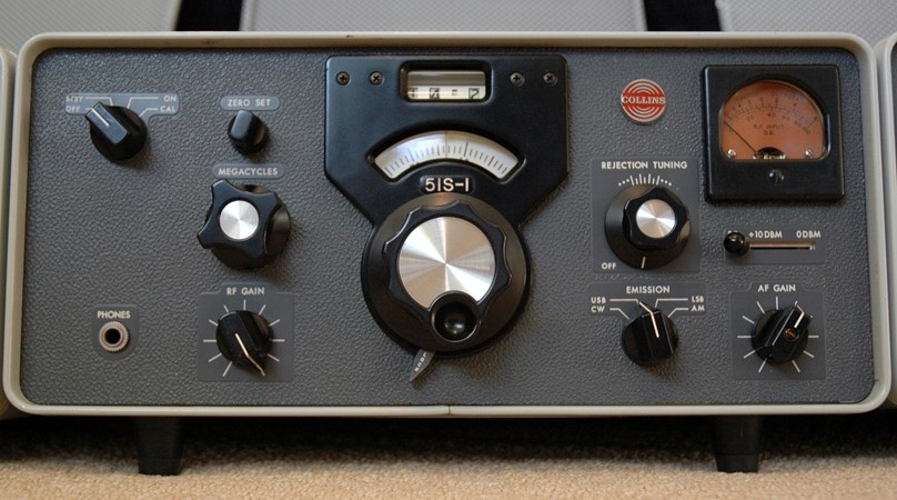
Figure 4 – Large Round Emblem 51S-1 Receiver
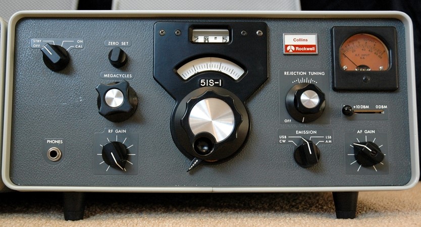
Figure 5 – Rockwell Collins Emblem 51S-1 Receiver
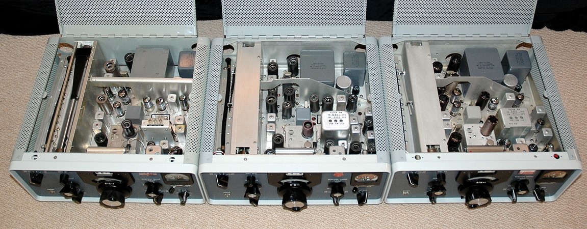
Figure 6 – WE, RE, and RC 51S-1 Receivers Lined up for Inspection
Tables 4 and 5 provide a list of publications on the 51S-1 receivers. Now that you can place your receiver in the production time frame, you can find the appropriate publications for it.
Table 4 – 51S-1 Instruction Manuals
| Models in Title | Edition | Date | Comments |
| 51S-1/1A/1F | 1st Edition | 1 Apr 1961 | 70K-4 PTO |
| Addendum to 1st Ed. | 28 Mar 1961 | AF Gain Control Change | |
| 2nd Edition | 1 Aug 1961 | ||
| 2nd Edition, Rev 1 | 15 Oct 1961 | ||
| 3rd Edition | 15 Dec 1961 | 70K-7 PTO | |
| Addendum to 3rd Ed. | 15 Feb 1962 | ||
| 51S-1/1A/1F/1AF | 4th Edition | 15 July 1962 | |
| Addendum to 4th Ed. | 1 Jan 1963 | Alternate L108 assemblies | |
| 5th Edition | 15 Aug 1963 | ||
| Supplement to 5th Ed. | 15 Feb 1965 | ||
| 6th Edition | 1 Mar 1965 | ||
| Supplement to 6th Ed. | 15 Feb 1965 | Identifies differences in 51S-1B & 51S-1 | |
| 7th Edition | 1 Nov 1965 | ||
| 8th Edition | 1 June 1967 | ||
| 51S-1/1A/1F/1AF/1B | 9th Edition | 1 July 1969 | |
| Supplement 1 | 15 Mar 1970 | ||
| 19th Edition | 15 Jan 1974 | ||
| 11th Edition | 15 Sep 1975 |
Table 5 – 51S-1 Service Bulletins and Service Information Letters
| Pub | Date | Applies To: | Subject |
| SB 1 | 02/22/63 | 51S-1 | Suppression of Unwanted Oscillations in Low-Level Audio Output Lines and Allow Use of Wiring Configuration Shown in Figure 1.2.a of Instruction Book |
| SIL 7-63 | 05/14/63 | 51S-1 | Reduced Hum in Audio Output With Use of 28-Volt DC Power Supply |
| SB 2 | 06/22/64
Revised 06/15/73 |
51S-1/1A/1AF/1B/1F | Replace Transformers T14 and T15 With Mechanical Filter |
| SB 3 | 08/11/64
Revised 08/31/64 |
51S-1/1A/1AF/1F | Improve Sensitivity of Lower Bands |
| SB 4 | 08/09/65 | 51S-1/1A/1AF/1F | Addition of Dial Lock Assembly |
| SB 5 | 04/01/70 | 51S-1/1A/1AF/1F | A: Converts 51S-1A/1AF to 51S-1/1F
B: Converts 51S-1/1F to 51S-1A/1AF |
| SB 6 | 09/01/71 | 51S-1//1F | Provision for High-Speed Receiver Muting and Recovery |
| SB 7 | 01/01/72 | 51S-1/1A/1AF/1B/1F | Reduce 500-kHz Spurious Response |
- CCA COLLINS HISTORICAL ARCHIVES
- The Pre War Years
- The War Years
- Post War Broadcast / Commercial
- The Black Boxes
- The Grey Boxes
- 30L-1
- 30S-1
- 312B-4/5
- 32S-3
- 51S-1
- 51S-1 Detailed Physical & Operational Description
- 51S-1 HF Receiver - Blocksome
- 62S-1
- 75S-3B
- Collins Microphones
- KWM-1
- KWM-1 Accessories
- KWM-2/2A Accessories
- KWM-2/2A Transceiver
- S Line Accessories
- The “S” Word or Solid State